
Although there are several computer applications that address this issue with field models, one of the most widely used is FDS (Fire Dynamics Simulator) developed by NIST (National Institute of Standards and Technology, USA) which is freely accessible. To facilitate data input and output from a graphical environment, there is a paid application called Pyrosim that uses FDS as the calculation engine.
Data Input
- Geometric representation: The first step consists of introducing the 3D geometry of the building or sector under analysis, as it establishes the boundary with its openings and distribution of interior elements in which the fire will be simulated and the development over time will be studied. Pyrosim facilitates the import of CAD files. Physical elements can be assigned materials that will determine their thermal behavior, which are defined as surfaces with their corresponding thicknesses and do not necessarily have to match the physically represented thickness of the element.
- Fire loads: it is necessary to introduce into the model the combustible elements existing in the rooms where the fire develops or may spread. These will represent the main fire loads that feed and determine its evolution. The program usually has a library of the most common materials with their main characteristics related to their fire behavior: combustion and vaporization enthalpies, pyrolysis reactions, heat release rates or mass loss rates, combustion products, and a long etcetera.
- Scenario hypothesis: the start and development of a fire depends on the confluence of a series of circumstances that can vary for the same scenario. There are initial conditions such as indoor and outdoor ambient temperature, wind, etc. Then there are conditions that can vary over time: rooms to include in the simulation process, selection of fire initiating elements, opening state of gaps between rooms or to the outside, initiation of ventilation and extinction systems operation, extinguishing agent discharge (water or gas)…
- Fire curve: defining the power that the fire will have over time is the fundamental element of the simulation, as it ends up being the “engine” that generates the flame and the high temperatures and gas velocities, so that underestimating this power leads to results lower than those possible in a real scenario. The curve can be defined as a “burner” surface that will have the power parameters over time that we preset, or the program can be allowed to calculate the propagation to new materials as the ignition temperature is reached in a cell where they are located. Likewise, fire extinction can be defined, either by temperature or by an experimental extinction coefficient.
- Cell meshing: space discretization affects the precision of results, as smaller cell size means greater accuracy. As a counterpart, this directly affects the time needed to calculate the simulation and the memory required to carry it out. Values of 15, 20 or 25 cm cell size are considered sufficiently precise to analyze fire smoke behavior in large volumes. In initial phases of the study, larger values can be used to reduce simulation time.
- Simulation duration: determines the real time of fire evolution to be calculated and which begins with the ignition of fire loads arranged as initiating elements. The FDS calculation engine analyzes both smoke and fire behavior, allowing data to be obtained for studying building occupant evacuation, or temperatures that may affect structural elements.
What data is obtained after the simulation process?
Once the FDS calculation engine finishes the simulation process, the program provides a series of parameters in data sheets (.csv) that can be visualized graphically as curves over time. Among the different data that can be obtained are:
- Smoke or heat detector activation.
- Sprinkler activation.
- Temperatures in the smoke layer.
- Clear height of smoke.
- Temperature in sprinklers or heat detectors.
- Degree of smoke obscuration in smoke detectors.
- Flows through openings.
- Temperatures on surfaces and inside structural elements over time.
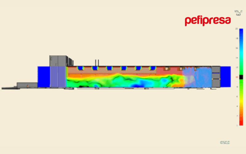
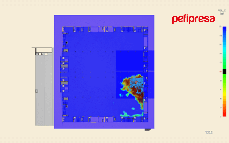
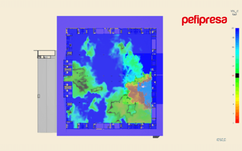
It is also possible to visualize graphically the 3D environment (through NIST’s Smokeview program or Pyrosim’s visualizer) representing the generated smoke and flames, the evolution of properties such as temperatures, velocities, smoke obscuration (or alternatively visibility), concentration of toxic combustion products in horizontal or vertical planes or in 3D coloring. These graphics allow the designer to analyze building behavior, its smoke evacuation and temperature control systems, the development of possible evacuation or firefighter intervention.
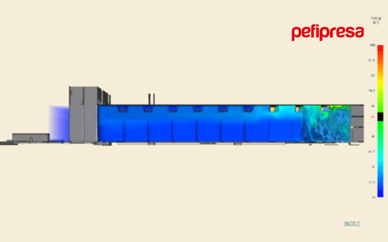
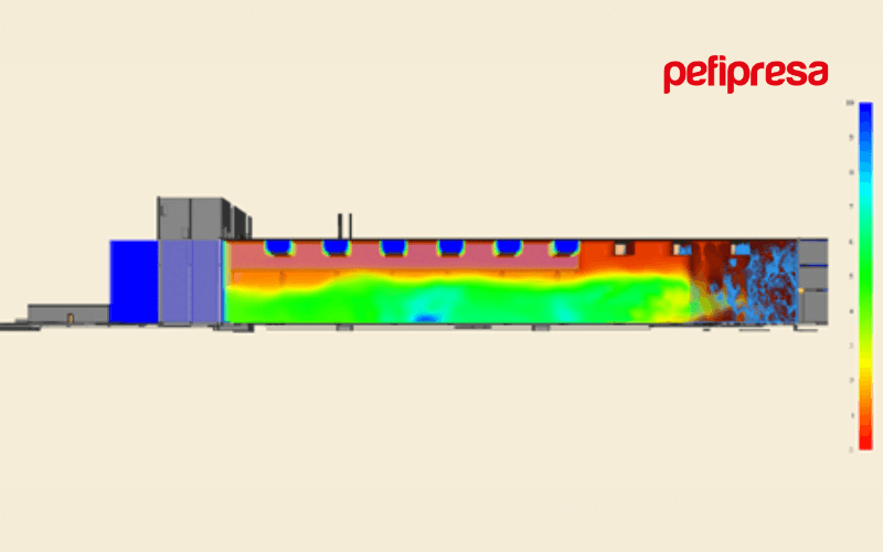
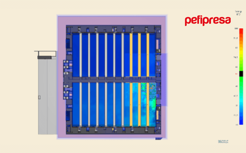
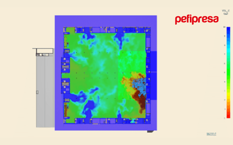
In the following images you can see a fairground enclosure of 17 m height and 23,000 m² with sprinklers and mechanical ventilation smoke evacuation system, in which conditions over time are observed for a high fire of 25 MW according to UNE 23585 that ends up activating 33 sprinklers.


Conditions for evacuation

Conditions for firefighter intervention (3,600 s)