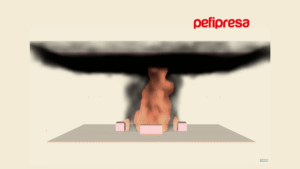

A fire in a datacenter is not measured in square meters burned, but in hours of service interruption and in the value of the information compromised. In the loss data FM Global compiles for this occupancy, fire heads the cost of losses while water and other liquid damage heads the frequency: two facts that already signal a datacenter isn’t protected like any other building.
The question raised in almost every project —”gas or water?”— is the wrong question. The protection strategy of a datacenter isn’t chosen: it’s deduced from the conditions the room actually meets.
In this article we walk through how that strategy is determined, which conditions enable each technology, and the two aspects most often missing from the specifications we receive: electrical power isolation and lithium-battery risk. We do it from the practical experience of Pefipresa, specialists in Fire Protection, for the profile who most often decides on these projects: the Facility Manager or CPD operations lead.
Why fire in a datacenter requires a different approach
Fire in a data center has three differential traits that condition the entire design:
- Prolonged incipient combustion: the most likely origin is an electrical fault —series arcing, a loose connection, high-resistance parallel arcing— that conventional electrical protection doesn’t always detect or clear. Before any flame develops there are minutes, sometimes hours, of pyrolysis of plastics and insulation, with very low optical-density smoke.
- Forced air flows: precision cooling moves large volumes of air that dilute smoke, carry it away from the source, and delay the response of conventional point detection.
- Extreme sensitivity to residue: an uncontrolled water discharge, or corrosive smoke from a PVC-jacketed cable, can disable electronic equipment to an extent equivalent to the fire itself.
That’s why the fire protection design for rack rooms and data centers is never solved with a single system, but with layered protection that detects earlier and acts while minimizing collateral damage.
The key decision: which conditions enable each technology
FM Global’s Data Sheet 5-32, in its current edition, resolves the debate through a decision tree that turns a preference-based discussion into a condition check. Simplifying its logic for above-floor room protection, gaseous agent or hybrid systems are only admissible as standalone protection if all of these conditions are met:
- The room is of noncombustible or approved-material construction.
- Cabinets and filler panels are noncombustible.
- Cold- or hot-aisle containment is noncombustible or of approved material.
- Cables are non-propagating and trays and raceways are noncombustible.
- There is no distributed Li-ion battery back-up in the cabinets.
- Automatic power isolation can be provided, or a manual plan meeting very strict conditions.
If any of these fails, the options narrow: gas and hybrid systems fall away first, then water mist, and in the worst case —multilevel cable trays present— only sprinklers or water mist under specific criteria remain. A parallel decision tree applies to concealed spaces: raised floor and above-ceiling plenum.
The value of this approach for a client is that it replaces a negotiation with a checklist. If they want gas, there are conditions their room must meet; if it doesn’t meet them, the conversation stops being about the extinguishing agent and becomes about the room’s materials.
One nuance that surprises anyone used to common commercial practice: the preference order for sprinklers is wet, non-interlock preaction, single-interlock preaction and, last, double-interlock preaction. The reason is the delay in water application, the added valve-equipment complexity, and the lower availability of the assembly. Double interlock is not the safer default: it’s the slowest.
Very high-sensitivity detection: the first critical layer
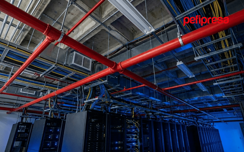
Aspirating smoke detection (ASD) simultaneously solves the low optical-density problem of incipient smoke and that of forced air flows. A network of pipes continuously samples air from the false ceiling, raised floor, return plenum and, when locating the event matters, from inside the rack cabinets themselves.
How it’s correctly specified in the European framework
Sensitivity is specified through the UNE-EN 54-20 classification (class A, very high sensitivity; class B, high; class C, normal), and detection system design follows UNE 23007-14, to which the RIPCI refers. Class A is standard in critical areas. The Anglo-Saxon equivalent, Very Early Warning Fire Detection (VEWFD), comes from NFPA 76, on telecommunications facilities, not from NFPA 75, on information technology equipment, which refers to NFPA 72 for detection.
Three parameters that decide whether the system works
- Air velocity. Forced ventilation must stay below roughly 1.5 m/s, or be interlocked to drop to that value on pre-alarm. The interlock must undergo an acceptance test at commissioning: leaving it merely programmed isn’t enough.
- Panel setting versus per-hole sensitivity. This is the most common commissioning error and is rarely explained. The usable sensitivity at each sampling point is not the one programmed on the panel: the setting must be divided by the number of holes, because only one is sampling smoke while the rest sample clean air. With fifty points, a 0.2 %/ft per-hole alert threshold requires programming the panel at 0.004 %/ft.
- Transport time. Transport time from the farthest sampling point to the detection unit must not exceed 60 seconds.
Added to this are coverage criteria per sampling point —roughly 18.6 m² with a single detection level, or 37.2 m² per level when two are used— and staged thresholds across alert, pre-alarm and alarm, which let the operator investigate, reroute load and reduce ventilation before any suppression acts. These values should be verified against the current edition of Data Sheet 5-32 at the time of the project.
Suppression options, and what conditions each one
Gaseous agents: what today’s fluorinated gas framework allows
Before discussing performance, it’s worth clarifying which agents are commercially available. Regulation (EU) 2024/573 on fluorinated gases lists HFCs in Annex I, and its Annex IV, point 11.c), sets 1 January 2025 as the date from which it’s prohibited to place on the market fire protection equipment containing or depending on these gases, unless necessary to meet safety requirements in the area of operation. In practice, HFC-227ea and HFC-125 are not today the reference option for a new installation in the EU.
FK-5-1-12 appears in Annex III, so it isn’t affected by that ban or by Annex I’s leak-control requirements, though it is subject to certification, training and notification obligations; its status under the proposed PFAS restriction under REACH should be tracked. It’s also worth specifying by technical designation rather than brand: “Novec 1230” is a 3M trademark, and 3M announced it would exit PFAS manufacturing by the end of 2025; the agent is supplied today by several manufacturers.
Inert gases (IG-01, IG-55, IG-100 and IG-541) work by reducing oxygen concentration, have zero GWP and ODP, aren’t affected by the fluorinated gas framework, and have an indefinite shelf life, at the cost of a larger cylinder-room footprint. They share a NOAEL of 43% and LOAEL of 52%, and UNE-EN 15004-1 limits maximum exposure time by design concentration: five minutes below 43%, three minutes between 43% and 52%, thirty seconds and only in unoccupied rooms between 52% and 62%, and no exposure permitted above that. Since typical design concentrations fall in the 40-48% range, the system always requires discharge delay, optical and acoustic pre-warning, signage, an abort switch and prior evacuation.
Water mist: tightly bounded application conditions
Regulated by UNE-EN 14972 and accepted for data processing rooms, but only within strict limits when using a system specifically approved for this application: maximum upward velocity around 1 m/s through the perforated floor, maximum horizontal flow around 1.2 m/s, no multilevel propagating cable trays, and no UPS or lithium batteries in the room. There’s no general design methodology for water mist: each system relies on the manufacturer’s full-scale testing, so only the system approved for the specific application applies.
Hybrid water and inert gas systems
Contemplated for data processing rooms under conditions similar to water mist, including the absence of UPS and lithium batteries.
Power isolation: the condition almost no one specifies
This is the point that separates a complete specification from an incomplete one, and it rarely appears in the specs we receive.
A gaseous agent extinguishes but doesn’t cool or de-energize. Concentration is held for a limited time —typically ten minutes— because building a tighter enclosure gets exponentially harder the longer that time runs. When concentration drops, whether from natural leakage or simply because a door opens for responding crews, the source can reignite if the equipment is still powered.
If a clean agent system is the room’s only protection and the equipment isn’t de-energized within the hold time, the expected outcome isn’t a contained incident: it’s an uncontrolled fire that spreads to the limit of the fuel present.
That’s why the criterion isn’t holding concentration for ten minutes, but holding it for ten minutes or until the equipment can be de-energized, whichever is longer. And why automatic power isolation, with an orderly shutdown within a maximum of ten minutes, is the preferred option.
When business continuity rules out automatic shutdown, a manual power-down plan is accepted, but only if every required condition is met: very high-sensitivity detection throughout all rooms, permanent supervision with immediate notification to responding crews, qualified personnel on site 24 hours a day authorized to execute the shutdown within a maximum of ten minutes, noncombustible construction, excellent facility management programs, and a plan agreed by management, reviewed annually, drilled at least once a year and timed at every drill. This isn’t a convenient alternative: it’s a demanding one.
Lithium-ion batteries: the scenario that changes the rules
Replacing lead-acid batteries with lithium-ion in UPS units, and especially the emergence of distributed backup units inside server cabinets themselves, introduces an ignition source that wasn’t previously present in the room.
The criterion here is an explicit prohibition: halocarbon, inert gas, or hybrid systems must not be used to protect rooms with distributed lithium backup units. There are three reasons. There’s no evidence that gaseous protection extinguishes or controls thermal runaway; the agent may interrupt the reaction, but only during the hold time, which isn’t enough to prevent thermal propagation to adjacent modules. Gaseous protection doesn’t cool, and cooling is the critical factor. And discharge is a one-shot event, while these fires can reignite hours after the initial incident.
The design criterion is clear: in rooms with distributed lithium backup, the suppression strategy is decided by water, not by gas. No volume of clean agent substitutes for sustained cooling.
The associated criteria affect the room’s layout: vertical steel barriers at least 0.9 mm thick every three cabinets along the row, a minimum 1.2 m aisle between rows, and a 20 kWh-per-cabinet threshold above which the installation stops being treated as distributed backup and is considered an energy storage system, with its own protection framework.
Critical design conditions for a gas system
- Discharge time and concentration. 95% of the design concentration must be reached within roughly 10 seconds for halocarbons and 60 seconds for inert gases. Design concentration is not extinguishing concentration: it builds in a safety factor by fire class.
- Enclosure tightness. The enclosure integrity test (door fan test, Annex E of UNE-EN 15004-1) verifies that concentration is held for the hold time. It must be repeated: every 36 months if a documented control program exists for envelope penetrations, or at least every 12 months if it doesn’t.
- Overpressure relief. Discharge generates a pressure transient capable of damaging the enclosure. It requires correctly sized and oriented relief vents, which must not be confused with or share ductwork with smoke extraction.
- Vaporization and obstacle distance. Halocarbons require vaporization distance and inerts require clearance. If the agent hits a surface before vaporizing, frosting occurs and the delivered concentration falls below the design value.
- Post-discharge ventilation. A plan and means must exist to ventilate the enclosure after discharge, including halocarbon decomposition products, without contaminating other areas.
Discharge noise and hard drives
This is a real, documented risk: in a known incident, inert gas discharge following an overheated HVAC condenser damaged storage system drives. Vibration displaces read/write heads off-track, causing them to strike the disk surface and making data unreadable.
Mitigation criteria are specific: noise-reducing discharge nozzles approved as a system component, regulated-pressure systems for inert gases, minimum radial distance calculated from the disk’s damage threshold —and, when that threshold isn’t known, 100 dB as the design value—, reference distances around 2 m for small-orifice diffusers and 3 m for large-orifice ones, and a ban on pneumatic sirens as a warning device.
Smoke evacuation: two radically different design criteria
In a room protected by gaseous agent, a smoke evacuation system running during the fire defeats the extinguishment: if air is being actively renewed, the design concentration never builds up or is lost immediately. FM’s criterion is consistent with this —do not install automatic-operation smoke evacuation in data processing rooms and, when local code requires it, interlock it with the water-flow alarm and never with the detection system— but it leaves the Spanish designer wondering how to reconcile this with a regulatory requirement.
The answer lies in the regulation itself, and it’s frequently overlooked. Section 13 of Annex I of the RIPCI doesn’t impose a single design criterion for smoke control systems: it lists several possible strategies. Letter a) is smoke control during the fire —thermal buoyancy and maintaining a smoke-free layer height, developed per UNE 23585. But letter d) expressly covers using these systems for smoke extraction after the fire, when an incompatible suppression system is installed relative to the other smoke-control types.
Incompatible suppression systems are considered to be those requiring a high degree of enclosure tightness to function correctly: exactly the case of gas extinguishing and aerosols.
The change of criterion isn’t a wording nuance, it’s a change of installation. A system designed under letter a) is sized by the mass flow of smoke that must be extracted to sustain a clear layer at full fire development. A system designed under letter d) is sized, as guidance, for an equivalent capacity of 2 to 10 air changes per hour. The difference in fan power, duct cross-section and installation cost is an order of magnitude.
And there’s a consequence that resolves the conflict at its root: a system designed to act after the fire doesn’t need to be interlocked with detection, because it shouldn’t start during the event. It’s also, in fact, the same system that serves the post-discharge ventilation plan required by insurer practice. A single installation covers both needs.
In practice this translates into four project decisions: declaring and justifying in the design report that the post-fire extraction strategy applies, evidencing the suppression system’s incompatibility; sizing within the 2-to-10-air-changes-per-hour guideline; fitting ducts with motorized dampers, fail-closed, interlocked with the extinguishing panel; and recording the full sequence in the cause-and-effect matrix, with extraction inhibited during discharge and the hold time.
Liquid cooling: the risk that arrives with AI
Direct-to-chip cooling, rear-door heat exchangers and immersion cooling are entering high-density datacenters, bringing with them a property risk that isn’t fire, but liquid: the loss category that, per FM’s compiled loss data, heads frequency.
Basic criteria affect the mechanical design: non-flammable fluids, noncombustible or approved piping, welded joints as the preferred arrangement, an explicit ban on push-fit interference connections, routing that avoids running over sensitive equipment, noncombustible leak containment with sufficient capacity and drainage, addressable leak detection with alarm at a permanently attended point, isolation of each supply line so a leak doesn’t compromise the rest, and monthly inspection of piping within the room.
Dedicated protection of electrical cabinets and rack cabinets
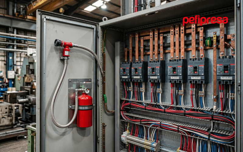
Systems for electric cabinet fire protection integrate linear heat-sensitive cable or microaspiration detection with autonomous extinguishing inside the switchboard’s own enclosure, so action occurs before the event affects the room. For environments where cabinets house critical equipment, automatic fire protection extinguishing systems for racks add a layer integrated into each cabinet, with its own detection and localized discharge.
Keep in mind that this layer doesn’t replace room-level protection or solve the lithium-battery scenario, and that installing aspirating detection directly in cabinets is expressly contemplated when locating the event or supporting manual power cut-off at the point of origin matters.
How it all comes together: the cause-and-effect matrix
- Layer 1 — Very high-sensitivity detection in the room: sampling in the false ceiling, raised floor and return plenum, with staged thresholds.
- Layer 2 — Detection inside critical assets: heat-sensitive cable or microaspiration in switchboards and high-density cabinets.
- Layer 3 — Room-level suppression: whatever the room’s conditions enable, not whatever is preferred a priori.
- Layer 4 — Electrical power isolation: automatic, or via a timed manual plan, without which the previous layers don’t close the scenario.
- Layer 5 — Coordination with operations: pre-alarms integrated with the control center, power cut-off plan, response plan and post-discharge ventilation plan.
The document that ties all this together is the cause-and-effect matrix between detection, suppression, HVAC, dampers and power cut-off. Its functional verification at commissioning, testing every line, is what distinguishes a correct project from one that only complies on paper. Its absence is, almost always, the material root of interlock conflicts.
Applicable regulations: the common framework
- RIPCI (RD 513/2017), in its version consolidated after RD 164/2025, for installation and maintenance of active systems, including the periodicities of its Annex II. Its Annex I, section 13, defines the admissible smoke control strategies, including post-fire extraction for enclosures with suppression systems requiring tightness.
- CTE DB-SI or RSCIEI, depending on use classification. This determination must be explicitly justified in the project. The RSCIEI currently in force is RD 164/2025, which repealed RD 2267/2004 with effect from 10 May 2025 and has been mandatory since 10 November 2025.
- Explicit requirement for rooms with electronic equipment. The RSCIEI has established the installation of gaseous agent extinguishing systems in fire sectors of industrial establishments constituting enclosures housing electronic equipment, computing centers, data banks, control or measurement centers and the like, when water protection could damage such equipment. Its exact numbering should be confirmed against the current text of RD 164/2025.
- UNE-EN 15004 (equivalent to ISO 14520) for gaseous agents, UNE-ISO 6183 for CO₂, UNE-EN 14972 for water mist, UNE-EN 54-20 and UNE 23007-14 for detection, UNE 23585 and UNE-EN 12101 for smoke control.
- Cable fire reaction in Euroclasses under Regulation (EU) 305/2011, with direct impact on the fire load of cable trays and raised flooring.
- Fluorinated gases: Regulation (EU) 2024/573.
- International references: NFPA 75 and NFPA 76; and, when required by the insurer, FM Global’s Data Sheets, in particular 5-32 for data centers, 4-9 for clean agents, 4-2 for water mist, 4-6 for hybrids, 5-48 for detection and 5-28 for battery systems.
As introductory Spanish-language material, NTP 975, published in 2013 by the then INSHT (today INSST), remains useful, always bearing its date in mind: it relies on the 1993 RIPCI, now repealed, and on the 2009 edition of UNE-EN 15004, and its considerations on halocarbon agents have been superseded by the current fluorinated gas framework. It is not a design criterion.
The editions of all these documents are reviewed periodically. Any specification must confirm the version in force at the time of the project.
A datacenter’s fire protection architecture is deduced at project stage, not chosen from a catalog. That’s why we approach every CPD from a prior technical consultancy phase, before any equipment is defined, verifying the room’s conditions, agreeing the power cut-off strategy and building the cause-and-effect matrix. Request a no-obligation technical assessment of your installation and we’ll work with you on the solution your installation’s risk profile actually enables.
Frequently Asked Questions about datacenter fire protection
Can I protect my room with gas alone and skip water?
Only if the room meets every enabling condition: noncombustible or non-propagating construction, cabinets, containment and cables; no distributed lithium batteries; and the ability to isolate electrical power. If any of these is missing, water protection —preaction sprinklers or water mist— stops being an alternative and becomes the available option.
Why is cutting electrical power so important?
Because gas extinguishes but doesn’t remove the ignition source. Concentration holds for a limited time, typically ten minutes, and when it drops —from leakage or because a door opens— powered equipment can reignite the fire. If power isn’t cut within that window, the gas system doesn’t close the scenario.
I have lithium batteries in my racks. Does my existing gas system cover that risk?
Not for that risk. The gaseous agent doesn’t cool, doesn’t prevent thermal propagation between modules, and only has one discharge, while these incidents can reignite hours later. The approach needs a full review: vertical barriers between cabinets, row spacing, verification of the per-cabinet energy threshold, and a water-based suppression strategy.
What is the enclosure integrity test and how often is it repeated?
It’s the tightness test that verifies the enclosure can hold the agent concentration for the project’s hold time. It must be repeated every 36 months if a documented program controls envelope penetrations, and at least every 12 months if it doesn’t: any subsequent building work or utility penetration alters tightness.
Can I install automatic smoke evacuation in a room protected by gas?
The real question is which RIPCI strategy applies to that enclosure. When the room is protected by a system requiring a high degree of tightness, such as gas extinguishing, the regulation allows using the system for post-fire smoke extraction, with a guideline capacity of 2 to 10 air changes per hour, instead of smoke control during the fire under UNE 23585. Since it acts after the event, no interlock with detection is required and activation is manual.